
- HOME > Instruction Manual > Chapter 2
- Chapter 2
Chapter 2. Reducer Instruction Manual
- 1. When the reducer is delivered, check
- 1) whether there is no damage during the delivery.
- 2) whether the specifications match the one named in the order list and whether there are no abnormalities.
- 2. Storage of the Reducer
- When the users have to store the reducer before the installation, pay close attention to the following matters.
- 2-1. short-term storage
- 1) Store the reducer indoors where the temperature change is low and it is dry. When the temperature change is high, the oil generates condensed moisture, which causes the damage to the oil function and the corrosion (rust) of gears, shafts, and bearings inside the reducer.
- 2) Check the inside by regularly opening the inspection window during the storage.
- 3) When the storage conditions are not good, refer to the long-term storage method.
- 2-2. Long-term Storage : Take the best measures during the long-term storage.
- 1) Disassemble the reducer and apply the anti-rust oil such as Metalgard 360(MOBIL) or ones equivalent to it to each unpainted part and case joint connection parts for storage. Clean it with a solvent or light oil beforethe assembly.
- 2) When kept indoors where the temperature change is low, the reducer does not need to be disassembled. The simplest way of storage is to fully fill the reducer with the used oil and seal the air vent.Apply the anti-rust oil such as Metalgard 360(MOBIL) or ones equivalent to it to the exposed input and output shafts.
- 3) When it is kept outdoors, completely remove the oil, unlock the upper (or left) case, then apply the Mobilarma 523, or 524 anti-rust oil to all parts that could be corroded before re-locking the case and sealing the air vent. Apply the Metalgard 360 anti-rust oil to the exposed shafts. The inside does not need cleaning but is filled with the really used lubricant as much as needed during the reuse.
3. Installation of the Reducer
- 3-1. Checks before the installation
- 1) Check whether the oil has been injected up to the leader line of the oil level gauge.
- 2) Turn the input shaft by hands or by means of simple tools. When the rotation condition is not good, disassemble it to review because inside defects such as assembly state or foreign debris are expected.
- 3) Check accessories and parts for the abnormalities of their attachment locations and functions.
- 3-2. Installation
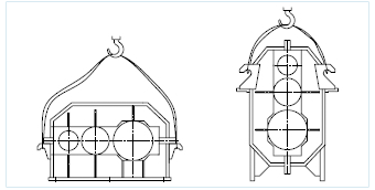
- 1) When carrying the reducer, use the lifting rings attached to the lower part of the case.Never hang any rope over the shaft. (Refer to Figure 1)
- 2) The foundation of the machine shall be a strong steel bed that is designed to sufficiently hold the variable loads and installed machines' weight, and be placed along with other machines on top of the same bed if possible.
 Picture 1
- 3) The foundation bolts shall be fastened securely with the even force by means of a torque wrench.
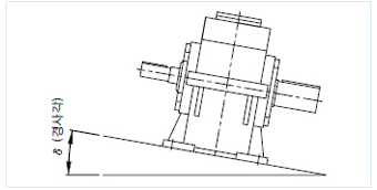
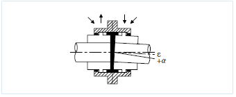
- 4) If possible, maintain the reducer's level horizontal without a square ∂ by using tools such as shim.(Refer to Figure 2)
- 5) When installing the input and output shafts by connecting them to their mating machines, hold the concentricity if possible. The eccentricity or angular displacement causes noises and vibrations, and furthermore, troubles to the lifespan of the couplings and the entire crane as well. Permitted amounts of the eccentricity and the angular displacement depend on the types and sizes of flexible couplings; therefore refer to the catalogue of the corresponding couplings or the instruction manual.
 Picture 2
Example 1) Gear coupling's range and tolerances
 Displacement
 Parallel offset : even though the driving and the driven shafts are parallel to each other, the centers are not matched.
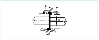
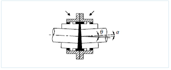
- Angular offset : the state where the driving and the driven shafts are tilted at an angle lying on the straight line.
- Axial flow offset : the state where the driving and the driven shafts move in the each axial direction.
- Multi offset : during the real operation, the above 3 or more offsets interact complexly.
Tolerance(S)
| S / Size | 140 | 160 | 180 | 200 | 250 | 280 | 315 | 355 | 400 |
|---|---|---|---|---|---|---|---|---|---|
| ε(mm) | 1.2 | 1.3 | 1.7 | 2.1 | 2.4 | 2.9 | 3.2 | 3.6 | 4.1 |
| θ(a) | 3(1.5) | 3(1.5) | 3(1.5) | 3(1.5) | 3(1.5) | 3(1.5) | 3(1.5) | 3(1.5) | 3(1.5) |
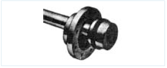
Example 2) Gear coupling's assembly procedure : After the precise inner diameter machining of the crown hub, choose the shrinkage-fitting or key-fitting. In the case of the key fitting, be careful about lubricant leaks around the key way.
① After cleaning all parts, apply grease to the tooth surfaces and o-rings before seating the o-rings.
- ② First, mount the internal sleeve onto the shaft then fasten it to the crown hub.(Mount the part with the standard mark to the outside.)
- ③ Adjust the angular offset to the permitted normal gap by using the thickness gauge.
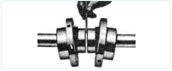
- ④ As shown in the figure, adjust the parallel offset every 90 in circumference by using a straight edge ruler so asto hold the offset within the tolerance specified at Table 1. Precisely align the shaft center with a dialgauge.
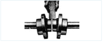
- ⑤ Interleave the internal sleeves with the gasket, apply grease to the crown gear, and then place the inlet at 90 before fastening the bolt.
- ⑥ Inject grease enough until the grease overflows on the opposite side of the inlet.
- 6) When mounting the coupling, sprocket, and pinion onto the input or output shaft, perform the shrinkage fitting, trying to avoid the force fit method if possible which delivers impacts to the reducer to finally damage the bearings, etc.
- 7) With respect to the method of connecting the reducer to its mating machine, the use of the pinion, sprocket and pulley onto the shaft end generates the overhang load. If possible, install them close to the reducer's main body. When assembling them far away from the main body, it causes the burden onto the shaft and the bearing to shorten the lifespan.
- 4. Operation Of The Reducer
- 1) Before the normal operation, perform the about 10-hour no-load operation then gradually the load operation.
- 2) Check whether the lubricating conditions are good through the inspection window attached to the upper case.
- 3)Switch the motor on and check whether the rotation direction matches the specified.
- 4)Check whether the motor's load current is within the rated current.
- 5)Check whether all functions work normally during the load operation.
- 5. Overhaul And Review
- The aggressive overhaul and review accounts for a great part of the extension of the reducer's lifespan. Initially finding problems and solving them before the damage occurrence are important. Record the results of the overhaul and review and refer to them in deciding the next repair and part replacement.
- 1) Daily Review
- - Noises of the gear and the bearing
- - oil leaks
- - Amount of oil and lubricating conditions (operating states of the oil pump)
- - Vibrations of the shaft and the case
- - Increase in a temperature
- 2) Weekly Review
- - Check whether or not the air vent is clogged.
- - Always clean the main body of the case.
- 3) Monthly Review
- - Check the oil for a degree of contamination.
- - Check whether or not the tooth surfaces have been damaged.
Table 1 . Installation Tolerances (mm)
| Size | 10 | 15 | 20 | 25 | 30 | 35 | 40 | 45 | 50 |
|---|---|---|---|---|---|---|---|---|---|
| Paralel | 0.125 | 0.125 | 0.25 | 0.25 | 0.3 | 0.3 | 0.3 | 0.3 | 0.3 |
| Angular | 0.125 | 0.125 | 0.25 | 0.25 | 0.4 | 0.4 | 0.5 | 0.5 | 0.5 |
| GAP (excluding the vertical type) |
3 | 3 | 3 | 4.5 | 4.5 | 6 | 6 | 8 | 8 |
- 4) Semiannual Review
- - Replace the oil and clean the case.
- - Check whether or not the tooth surfaces have been damaged.
- 5) Annual Review
- - Check the toothed gear for its wear.
- - Check the bearing for its damage.
- - Replace the oil and clean the case.
- - Check the foundation face and the locking conditions of the foundation bolts.
- 6. Lubricant
- The lubricant is a crucial role in extending the reducer's lifespan and any other parts and the specified one shall be used according to the use conditions.
- 1) Lubricant's roles inside the reducer
- - Prevent the friction caused during the toothed gear's interlocking rotation.
- - Absorb heat.
- - The formed oil film protects the tooth surface of the bearing or the toothed gear.
- - Prevent corrosion (rust).
- 2) Lubricant temperature inside the reducer
- - If the ambient temperature and air circulation conditions are not bad, the lubricant may bear a rise in the temperature by up to 40℃.
3) Recommendable Lubricants
| Type | Name of the company / ambient temp. |
-10℃ ~ 15℃ | AGMA | 10℃ ~ 50℃ | AGMA |
|---|---|---|---|---|---|
| Small size | Hankook Shell Oil Co., Ltd. Korea Houghton Corporation Caltex |
OMALA 150 M.P.G. 150 MEROPA 220 |
4EP | OMALA 220 M.P.G. 220 MEROPA 220 |
5EP |
| Medium size | Hankook Shell Oil Co., Ltd. Korea Houghton Corporation Caltex |
OMALA 150 M.P.G. 150 MEROPA 220 |
5EP | OMALA 220 M.P.G. 220 MEROPA 220 |
6EP |
| Large size | Hankook Shell Oil Co., Ltd. Korea Houghton Corporation Caltex |
OMALA 150 M.P.G. 150 MEROPA 220 |
6EP | OMALA 220 M.P.G. 220 MEROPA 220 |
8EP |
- 4) Lubricant mangement
- The review and management of the lubricant plays a very crucial role in extending the reducer's lifespan.
The lubricant contamination may occur for various reasons, usually by - - intermixture of metal particles caused by the wear of the gear and the bearing
- - viscosity shortage caused by gradual degradation of the viscosity
- - condensed moisture caused by temperature changes
- Using the contaminated oil may result in the fatal damage to the bearing and the toothed gear; therefore, follow the replacement cycle. The ideal way of managing oil is to collect and analyze samples regularly in order to examine the extent of the contamination.
7. Use Limits Of Parts
- 1) Toothed gear
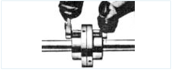
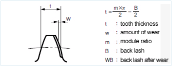
- The limit of the toothed gear's lifespan by the wear is usually 30 %, but it is decided by considering the degrees of the importance and danger according to functions. The range of the back lash of Joilreducer's reducer is 3/100~7/100 of the module, so the extent of the wear is judged by measuring the back lash regularly. In addition, the pinion and the gear are always combined in a pair and the extent of the wear may be different depending on the differences of the hardness and gear ratio of each pinion and gear. But all toothed gears produced by Joilreducer are profile shifted toothed gears designed to make the pinion and gear have the same lifespan. Therefore, decisions about the use limits are made according to the functional types of reducers by means of the measurement of back lash. When it is hard to measure the back lash, refer to the figure for the decisions.
- Example 1) Hoisting reducer (hoisting, boom hoisting) Luffing reducer
- - Decision by the amount of wear
- w = t × 1/10 = m × 0.16
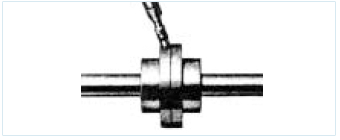
- - Decision by measuring back lash
- WB = m × 0.32
- Example 2) travelling reducer, transverse reducer, circular reduce
- w = t × 2.5/10 = m × 0.40
- WB = m × 0.80
- However, sometimes the amounts of the pinion and the gear are different, so when the wear differential is high with the naked eye, the severely worn toothed gear is the base for decision. When the toothed gear is replaced, the paired pinion and gear shall be replaced at the same time. If they are replaced separately, it causes noises and vibration, leading to the risk of damage due to the poor meshing state. The causes of the noise and damage by the toothed gear are as follows.
- A. Noise
- 1) irregular tooth meshing
- 2) improper back lash
- 3) damaged tooth surface
- 4) insufficient or improper lubrication
- 5) when the reducer assembly is not secure
- B. Damaged tooth surface
- ① Pitting (refer to Figure 3)
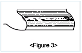
- The pitting occurs during the initial operation. When some teeth make a biased contact, the meshing parts have the overload. The overload spreads in the direction of the root circle from around the pitch circle to the entire gear. As shown in the figure, the small and round face peels off from the tooth surface. If it occurs at the biased contact, progresses in the direction of the face width for a certain period, and stops, it does not affect the hardness of the toothed gear. When the pitting has been found, replace the used oil with the new one that has higher viscosity. If the pitting progresses fast and continues to occur at the whole face widths, it means the overload operation. So the load has to be reduced.
- ② Scoring (refer to Figure 4)
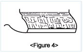
- The causes of the scoring are the lubricant's viscosity shortage, nonconformity, the toothed gear's hardness shortage, and flammable materials. Just as shown in the figure, the damaged shiny surface may be checked with the naked eye. Take immediate measures tight after finding the occurrence and first check the lubricant conditions because the main cause is the defective lubricant. If the problem does not come from the lubricant, quality of the materials or hardness causes the problem. If the lubricant is the main cause, it comes from the viscosity degradation by high heat, viscosity loss by long-term use and by the corrosion generated by using the improper oil instead of the gear oil.
- ③ Scoring (refer to Figure 5)
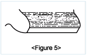
- The tooth surface fatigue, partial tooth meshing, etc. are the causes of the spalling that occurs when the toothed gear's surface has been hardened. It occurs at the boundary of the hardened and non-hardened layers, which ranges more widely than pitting, has angular shapes, and develops lengthways in the direction of the face width. Because it develops drastically at some part of the gear and causes very risky damage, replace the toothed gear right after finding the phenomenon. That is the main cause of the damage to the hardened toothed gear.
- ④ There are some other causes of damage but the aforementioned damage types account for mostof thedamage; therefore, if different types of damage are found, inquire of or contact Joilreducer formore information.
- 2) Bearing
- - Hoisting reducer : The regular overhaul period is within 25,000 hours.
- - Travelling and transverse reducers : The regular overhaul period is within 25,000 hours.
- - Check the bearing for the abnormalities by the regular review because the bearing may get damaged by unexpected abnormalities of the oil, toothed gear, and external factors.
- 3) Oil seal
- ① one year or regular overhaul period
- ② When oil leaks occur due to unexpected abnormalities, replace the oil seal and analyze the causes together.
- - defective oil seal
- - concentricity
- - shaft's surface roughness, etc.
- 4) Oil
- - regular replacement period: replace the lubricant for the first time in 100 hours after the start of operation. Since then, choose the replacement period of 1000~1500 hours or 6 months, whichever is faster.
- - Take some measures according to the component analysis results of collected samples.
- 8. Disassembly
- Start disassembling the reducer after being well-informed of the functions of all parts.
- 1) First, completely discharge the oil in the reducer through the drain plug.
- 2) Separate the upper case (left case) from the lower case (right case).
- 3) After disassembling by parts, tag each part in order to distinguish them from other parts.
- 4) Put small-sized parts such as bolts, nuts and so forth in a container so as not to be lost.
- 5) Keep all the parts away from pollutants.
- 6) In particular, pay close attention to the tooth surface not to get damaged.
- 7) After the disassembly, perform the entire review to check the bearing's wear and the case's cracks, then record the results of the review so as to use them during the part repair or replacement.
- 9. Assembly
- roceed with the assembling the reducer in the reverse direction of the disassembly while paying attention to the special matters handled in the disassembly process.
- 1) Before the assembly, clean up all parts.
- 2) Take care not to let small-sized parts such as bolts and nuts enter inside of the reducer.
- 3) Apply the liquid gasket such as ThreeBond 1104 or ones equivalent to it to the case's or the bear cover's contact face to prevent oil leaks.
- 4) When replacing parts such as part exchange, fasten the bearing cover onto the bearing with a clearance of 0.1mm or less.
- 5) Securely lock all bolts using an even force through a torque wrench.
- 6) If possible, inject new oil. When continuing using the used oil, fully filter it through a filtering device before reusing it.
- 7) After the completed assembly, check the input shaft for the abnormalities by turning it manually or in a simple way.
- 8) Check all the accessories and parts for the abnormalities of their locations and functions.
- 10. Reducer's Shutdown, Causes, and Countermeasures
| Shutdown | Cause | Countermeasure |
|---|---|---|
| When the main body heats | - overload operation - lubricant shortage or excess - defective or improper lubricant - defective or improper lubricant When the oil seal has no oil |
- Adjust the load properly. - Follow the leader line of a oil level gauge. - Replace the old, polluted lubricant with new one. - Inject more lubricant. |
| when the abnormal sound is serious | - regular sound/ defective Chiseochok bearing damage - high metallic sound/ too small release bearing lack of the lubricant - irregular sound/ water inflow bearing damage |
- Notify the manufacturer of the correction of Chiseochok - bearing replacement - Stop lubricant injection - debris removal, lubricant replacement - earing damage by wear - Notify the manufacturer of the bearing replacement. |
| When the vibration is high |
- tooth wear - debris inflow - bearing damage by wear - oosened fastening bolt |
- Notify the manufacturer of the toothed gear replacement. - debris removal, lubricant replacement - Stop lubricant injection - bearing replacement - Fasten the bolt. |
| When the lubricant leaks | - oil seal damage - packing damage - defective drain valve joint - oil gauge damage |
- oil seal replacement - packing replacement - Secure the locking - oil gauge replacement |
| When both the input and output shafts stop | - deposit of tooth surface - bearing damage - solid inflow |
- Correct or replace the toothed gear according to the degree. - Notify the manufacturer of the bearing replacement. - debris removal, cleaning inside, oil replacement |
| When the input shaft idles and the output shaft does not rotate | - wear of worm toothed gear - damage to the worm toothed gear's boss and shaft's key - The input shaft or worm is broken. - The output shaft is broken. |
- Notify the manufacturer of the toothed gear replacement - key replacement - Notify the manufacturer of the shaft replacement. - shaft replacement. |
| When the wear occurs | - in overload conditions - improper or defective lubricant -shortage of the lubricant - bearing wear - increase in the operating temperature |
- Adjust the load properly. - lubricant replacement - lubricant supplement - Notify the manufacturer of the bearing replacement. - Provide good ventilation. |