- HOME > Product > Geared Motor > JK - LT / BC
- JK - LT / BC
 JK-LT
JK-LT
- JK-BC
![]() Chapter 3 Geared Motor Disassembly Procedure and Exploded Views
Chapter 3 Geared Motor Disassembly Procedure and Exploded Views
- JK-BC
- The axial direction of this type is horizontal. When a brake or clutch is mounted onto the motor that is equipped with a reducer, operation and shutdown are possible. This type is the ideal product that also maximizes and optimizes the output revolutions, location and space needed when the users design and install.
- Caution Notices During the Use
- In this case when the reducer's input shaft is connected to the motor's output shaft, chains or belts are usually used. The chain or belt, connected to the reducer's input shaft and the motor's output shaft, is used in order to match the rotation of the driven body. When the ratio of the chain to the belt is not 1:1, it causes a big problem. Therefore, please be careful.
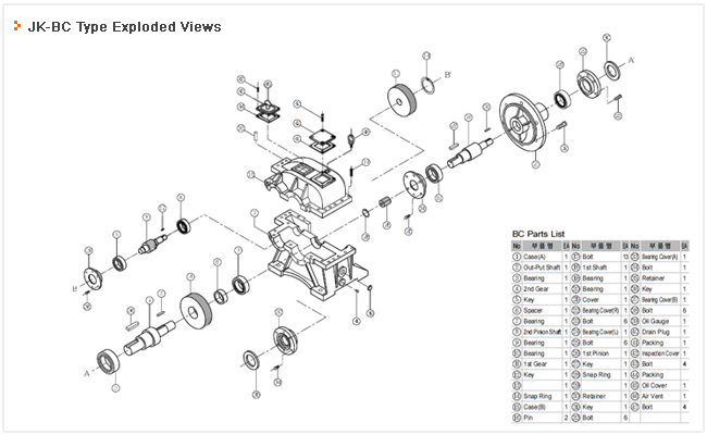
- JK-BC Disassembly Procedure
- First, with respect to the coupling of the reducer’s input and output shafts, unscrew the No.43, No.47bolts from the No.15case as shown in this view. Remove the No.42, No.45inspection covers, then take apart the No.41 No.44 packing, and unfasten the No.40plug of the No.1case to extract the oil. Unscrew the No.32, No.34 and No.38bolts from the main body, then the No.17bolt that is locked onto the No.15case, then take out the No.16pin to separate the No.21flange from the case. And if the No.15upper case is taken apart, the covers of the No.33 No.37 bearings are separated. And take out the No.8shaft from the case, remove the No.14ring, separate the No.12key from the No.11gear, then disassemble the No.9, No.10 B/R, take out the No.2shaft from the case, and disassemble the ㉠bearing in No.6, No.4, and No.5 order. Unfasten the No.28ring from the No.21flange assembly; disassemble the No.26pinion and the No.27key to remove the No.23, No.24covers. Then separate the No.18shaft from the No.21flange and unfasten the No.19, No.20B/R from the No.18shaft. Clean the disassembled product with cleansing oil and replace the worn parts with new ones, then clean the inside of the case before the assembly. Use a gasket in the case’s attaching face and pay close attention to preventing oil leaks during the assembly process. The assembly procedure is the reverse direction of the disassembly. Refer to the exploded view. New lubrication injection is a must.
- Lubricant’s Features and Replacement Period
- The use of bad lubricants or improper oil results in the damage to gears and bearings and causes abnormal temperature and connection, leading to shortening of the reducer’s lifespan.
- 1. Amount of fueling oil : always keep the flow rate up to the center of the oil level gauge located on the side of the case.
- 2. Oil’s replacement period : When the new product runs first, the fine initial worn part flows into the lubricant. Replace the oil in 100 hours after the first operation of a new product, and since then, every 1,000~1,500 hours.
- 3. Other matters : With respect to the product that needs different proper oil, please refer to the mark with Handle with Care that is specified on delivery.